Robot design overview:
Shooter:
The shooter is much stronger as it uses poly carbonate rather than the inflexible acrylic. This shooter yeilded results of 3/5 in its first testing but can be raised with some minor changes.
This current robot layout will be changed in the future:
Shooter Robot
The current design of the robot will be the 2 motor 4 wheel drive H chassis (because it is shaped like an H). The intake system will be in the very front, centered, and near the ground. This system will lead the particles directly, or almost directly, into the shooting mechanism, which will take up the whole center of the robot. The mechanism for pressing the beacon during autonomous will be on the right side, near the top, and centered relative to the right side. The spacing between this autonomous beacon mechanism and the shooting mechanism will be really small, and the shooting mechanism may have to be moved a few centimeters to the left, depending on the autonomous beacon mechanism. There will be a separate teleop beacon mechanism, one straight beam, on the very back of the robot, set to the same height as the beacon’s buttons. The purpose of the two beacon mechanisms is so that the teleop beacon pressing will be fast, since the autonomous has to be an active mechanism which is slower than the teleop. If this design persists throughout later into the season, the cap ball mechanism will be added onto the left side of the robot. Electrical parts will be in the center bottom of the robot.
Summarized:
- H chained chassis, 2 motor 4 wheel drive
- Harvester front center
- Shooting mechanism dead center
- Autonomous beacon right and top
- Teleop beacon back and top
- Cap ball mechanism (Maybe) on the left side
- Electrical components on bottom center
As for the first few meets, or early on the season, if the shooting mechanism is not ready before cap ball mechanism, the robot will follow this layout:
Cap Ball Robot
Same H shaped chassis, but the cap ball mechanism will be in the front. Autonomous beacon mechanism will be on the right top, and the teleop beacon mechanism will be on the back top. There will be no harvester or shooter.
Summarized:
- H chained chassis, 2 motor 4 wheel drive
- Cap ball mechanism at the front (will take up the whole front)
- No harvester or shooter
- Beacon mechanisms in the same positions as the first design
If this design works successfully, a design where the intake system for particles will be in the back, underneath the teleop beacon mechanism will be more thoroughly considered. The shooter will be in the center.
Design recap:
Whether the robot will start off as the shooter robot or the cap ball robot will all be based on whether the shooter or the cap ball mechanism will be completed first successfully. My estimations are that the cap ball robot will be the first design, since the shooter mechanism and harvester mechanisms are a little more complicated, spacious, advanced, and unknown.
Cap ball mechanism:
This is the only mechanism that is not documented yet. It will consist of 4 linear lifts (the same linear lifts used in the Res-Q South Super Regionals). Going from the South Super Regionals to the Texas Robot Roundup, the linear lifts were changed to a different kind because:
- The previous versions were a little heavy
- The previous versions were more prone to tilting
However, after the Texas Robot Roundup, the benefits for the Super Regionals linear lifts were clearer:
- The previous versions were faster
- The previous versions never untangled and were more consistent
Unknowns for the cap ball mechanism’s linear lifts:
- This will be the first time using 4 linear lifts of this kind, since during the South Super Regionals only 3 were used, meaning there might be unexpected results for torque
Cap ball intake mechanism: Here are the current designs:
Ring design
Sketch:
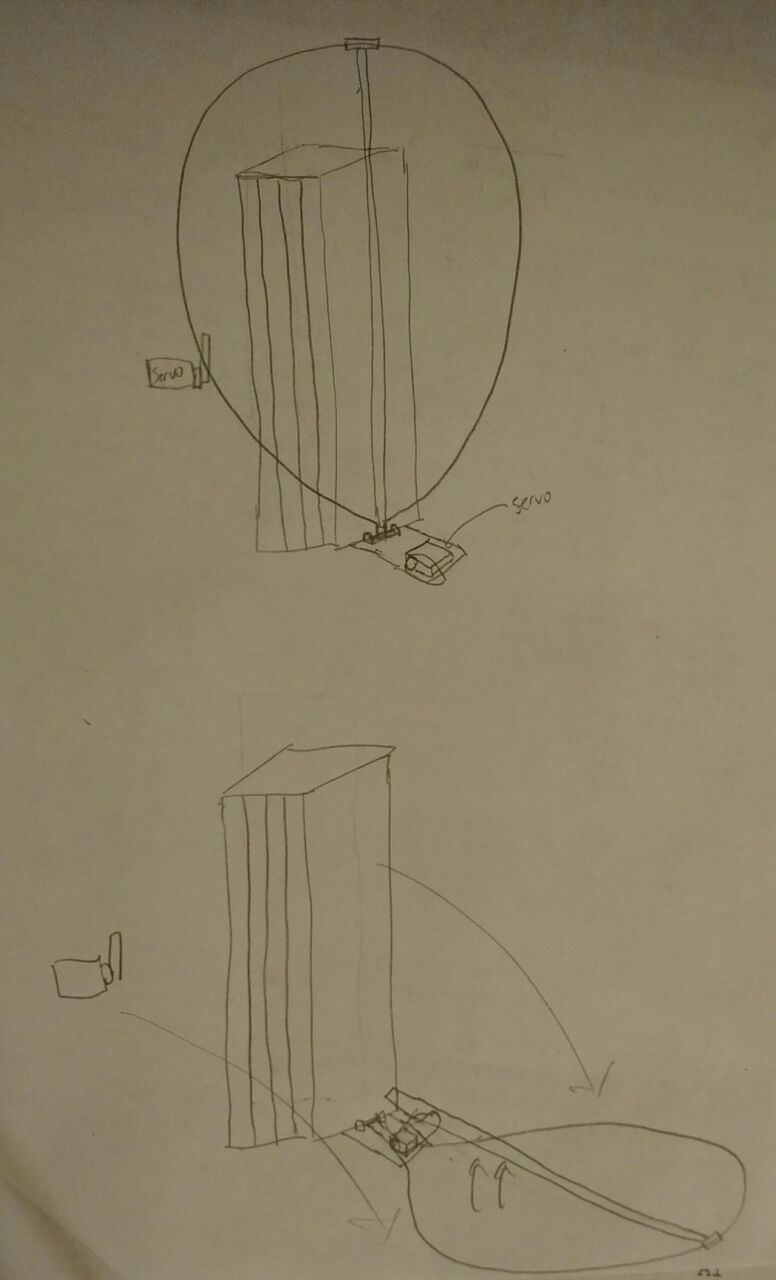
A ring that pivots on one point, which is the bottom of the linear lift. The ring starts off upright against the linear lift, and then when it is needed a servo will let go of the right, so that the ring rotates downward from gravity. There will be metal on the bottom of the linear lift that prevent the ring from going past parallel to the ground. Once the ring is parallel to the ground, the robot will drive the ring under the ball, so the ball might roll into the ring. Once the ball is sitting on the ring, the linear lifts will extend all the way up. Now the ring will have a small piece of metal going from one end – the furthest point from the linear lift – to the point closest to the linear lift, right next to the pivot point. At this point, the cap ball is resting on the ring, barely touching the metal beam or stick right below it. Once the cap ball is barely outside of the perimeter of the vortex, a servo will raise one end of the metal beam, the end that is on the pivot point side, so that the beam will be inclined. Because of this, the ball is expected to roll off into the vortex.
Unknowns:
- The linear lift may require more than one standard Andymark motor to lift the 4 linear lifts and the cap ball and the ring and the servo
- The ball might fall off during the linear lifts’ trip upwards
- The ball might roll off the right uncontrollably
Claw design
There will be the same 4 linear lifts on the same position, the front. However instead of a ring, there will be two large servos that will each be connected to two long beams that have rubber and other grippy materials. The two arms will be as long as possible, over 18 inches (they will be diagonal). The robot will drive toward a ball and pin in against a wall, so that the ball won’t move. The two servos will then move and the arms will wrap around the ball, just below its center. Then the linear lift will move all the way up, the robot will drive forward so that the cap ball is directly above the vortex, and then the two arms will separate at the same time.
Unknowns:
- The linear lift may require more than one standard Andymark motor to lift the 4 linear lifts and the cap ball and the ring and the servos
- Arms may not be strong enough
- Not enough room for the two arms
- Ball may become lose on its trip upwards
Cap ball mechanism recap:
There are currently two designs for the cap ball mechanism. The first one that will be tested is the ring design, since there will be less variables and less spacious.
Harvester/Transporter Mechanism
- Build basic attachment this week:
- Use four wheels from tread kit and attach two each to two flat channels
- Attach rubber bands around the wheels to move the ball (will be in between the rubber bands)
- Attach sponges around the wheels to keep to rubber bands in place
- Use flat channel to attach the two parts together, attach aluminum behind channels for the ball
- Base on Lego model and sketch
This will be the mechanism in front of the robot to bring in the particles and transport them to the shooter.
To Consider:
- Traction of rubber bands, may experiment with duct tape, rubber tubing, etc.
- Distance of wheels, how long the harvester will be
(insert sketch and photo)
Other mechanisms:
- Autonomous beacon mechanism: Currently undecided. Position is decided (right and top)
- Teleop beacon mechanism: One channel. Already functional. (Back and top)
- Shooter mechanism: Follow Abhishek’s progress recorded in the last week’s post. (Center)
- Harvester mechanism: Follow Amanda’s progress recorded two weeks ago. (front center bottom)
- Cap ball mechanism: In progress, currently somewhat decided. (depending on robot pathway, left or front)
Autonomous beacon mechanism description
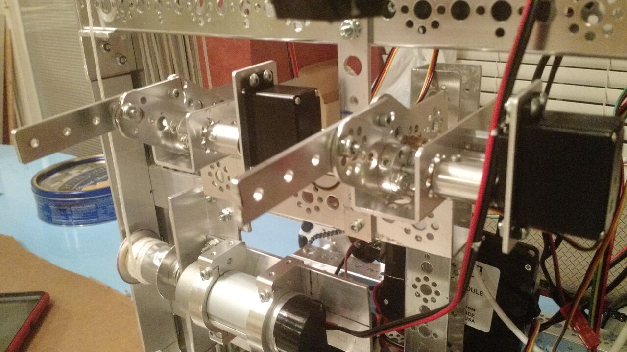
There are two standard sized servos that are mounted onto the robot with Tetrix’s front servo mount that connects the servo directly to an axel to increase the servos’ lifespan and strength. When these two servos rotate they also rotate an axle, which has an axle hub attached, which has a short tetrix 3 big holed flat beam. There is an identical beam a few wholes down, and the ends of the two beams connect to a stronger beam, which moves somewhat laterally when the servo rotates.
Picture:
Before extended:
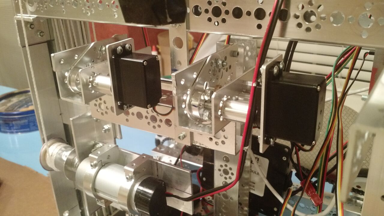
After extended: